
Pakistan is experiencing rapid industrialization, modernization of agricultural irrigation systems, and intensive...
Latest posts
-
 Advanced Flow Measurement Solutions in Pakistan: Industrial, Agricultural, and Commercial ApplicationsRead more
 -
 Pressure Transmitter Price in Pakistan: Complete Buying Guide, Types, Brands, Accuracy, Range & ApplicationsRead more
If you are searching for pressure transmitter price in Pakistan, the first thing to understand is that there is no...
-
 Industrial Valve Engineering & Procurement Guide: Most Commonly Used Valves across Pakistan's Process IndustriesRead more
Industrial flow control systems represent the lifeblood of modern process engineering. Across Pakistan's rapidly...
-
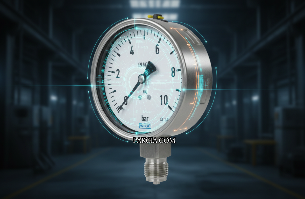 Selecting an Industrial Pressure Gauge in 7 Steps: The Ultimate Engineering GuideRead more
In any industrial processing plant, manufacturing facility, or automation loop, pressure is one of the most critical...
Blog categories
Search in blog
Archived posts
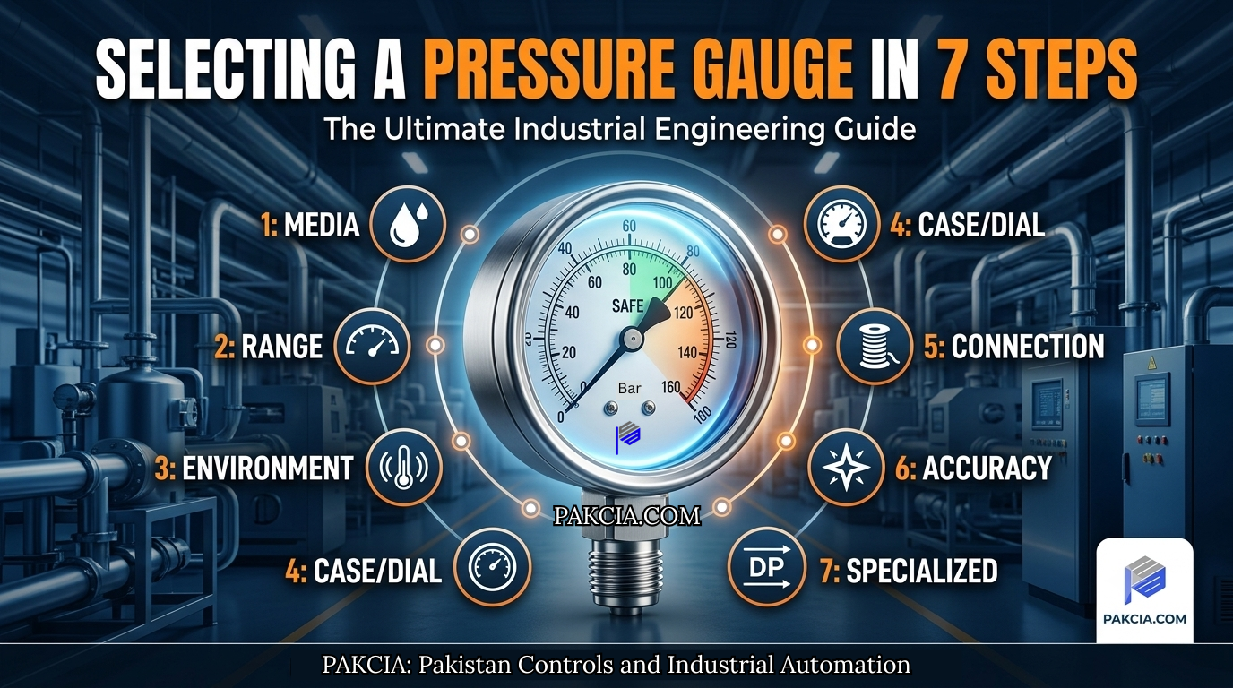
Selecting an Industrial Pressure Gauge in 7 Steps: The Ultimate Engineering Guide
In any industrial processing plant, manufacturing facility, or automation loop, pressure is one of the most critical physical variables to monitor. Incorrect pressure readings can lead to compromised product quality, system inefficiencies, and catastrophic equipment failures. While modern control systems rely heavily on digital transmitters, the humble analog mechanical pressure gauge remains your frontline defense for localized, fail-safe visual inspection.
However, selecting the right pressure gauge is not as simple as picking a random dial out of a box. Mechanical gauges operate in harsh, volatile environments where they face continuous pressure spikes, aggressive chemicals, mechanical vibration, and extreme thermal cycles. Specifying the wrong instrument can lead to rapid gauge failure, fluid leaks, or unsafe plant operations.
To ensure your instrumentation operates with maximum accuracy and longevity, this comprehensive, step-by-step engineering guide walks you through the 7 essential steps for selecting the perfect industrial pressure gauge for your specific applications.
The Critical Role of Proper Gauge Specification
Before diving into the steps, it is essential to understand why pressure gauge specification matters to both plant engineers and procurement managers. As a leading industrial pressure gauge supplier Pakistan businesses trust, PAKCIA frequently helps maintenance, repair, operations (MRO) teams, and engineers who face premature instrument failures. More often than not, these failures are not caused by manufacturing defects, but by an incorrect mismatch between the gauge's technical specifications and the actual process environment.
By implementing a structured engineering evaluation, you protect your plant from:
- Mechanical Fatigue: Diaphragm or bourdon tube ruptures caused by unexpected pressure surges.
- Chemical Incompatibility: Process fluids corroding the internal wetted parts, causing toxic or flammable leaks.
- Reading Inaccuracies: Choosing the wrong accuracy class or dial size, making it impossible for field operators to take reliable manual readings.
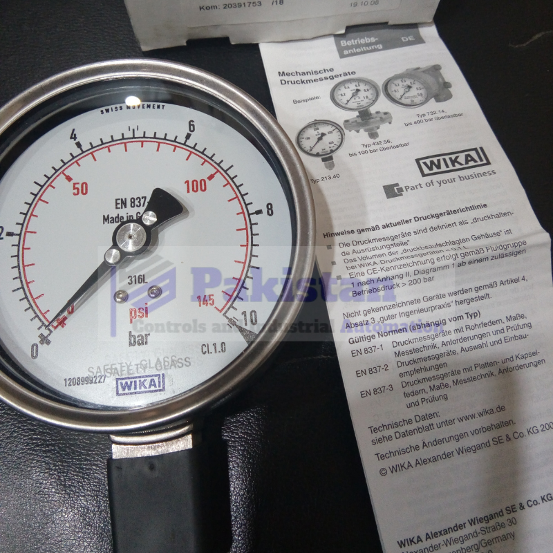 |
Featured Solution: WIKA 232.50Model: 232.50.100 |
Let’s break down the exact 7-step matrix required to choose the right mechanical instrument for your system.
Step 1: Understand the Process Media (Chemical Compatibility)
The very first factor to analyze is the nature of the fluid or gas that will come into direct physical contact with the inside of the gauge. This process fluid is known as the wetted parts media.
Mechanical pressure gauges typically use a Bourdon tube, capsule, or diaphragm element that flexes under pressure. If the process media is highly corrosive, abrasive, viscous, or prone to crystallization, it will rapidly degrade standard materials.
Common Wetted Parts Materials:
- Copper Alloy (Brass/Bronze): Ideal for non-corrosive gases and liquids such as standard water lines, compressed air loops, and light oils.
- Stainless Steel (SS316 / SS316L): The industrial standard for harsh environments. It offers excellent chemical resistance against aggressive media, high-temperature steam, and chemical compounds.
- Exotic Alloys (Monel, Hastelloy): Reserved for highly severe chemical processing, such as hydrofluoric acid or sour gas (H2S) applications.
Engineering Tip: If your process media is highly viscous, sanitary (food/pharma grade), or contains suspended solids that could clog a narrow Bourdon tube, you must isolate the gauge using a diaphragm seal (chemical protector). The diaphragm seal transfers process pressure to the gauge via an internal fill fluid (like silicone oil), protecting the delicate internal components from direct contact.
Step 2: Determine the Operating Pressure Range
To guarantee safety and instrument longevity, a pressure gauge should ideally operate within the middle third of its total scale range. In other words, your normal, day-to-day operating pressure should equal roughly 50% to 65% of the maximum dial limit.
The 2x Rule of Thumb:
As a general standard regulated by ASME B40.100 and EN 837-1, select a gauge with a maximum full-scale range that is twice (2x) the expected normal working pressure of your system.
For example, if your steam line normally runs at 8 Bar, do not buy a 0-10 Bar gauge. Instead, source a 0-16 Bar or 0-25 Bar instrument.
Why is this scaling headroom necessary?
1. Prevents Fatigue: Operating continuously near the absolute maximum limit causes the internal measuring element to lose its elasticity over time, resulting in permanent zero-point calibration drift.
2. Accommodates Surges: It provides a safe buffer zone for unexpected overpressure spikes or hydraulic water hammer without rupturing the internal tube.
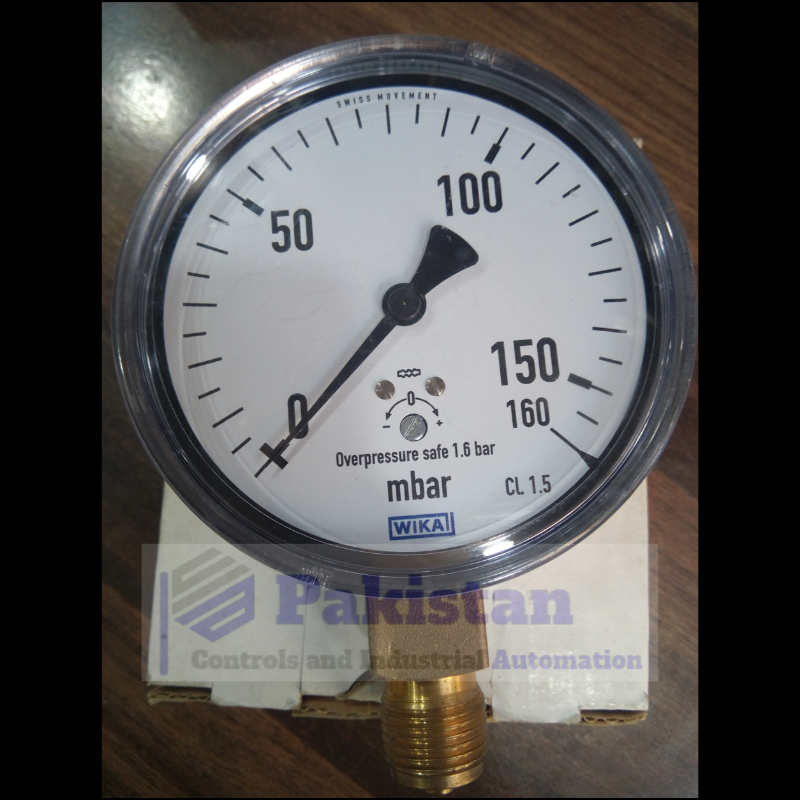 |
Featured Solution: WIKA 160mbarBrand: WIKA |
Step 3: Assess the Environment (Temperature, Vibration, and Weather)
The ambient conditions surrounding the outside of the gauge case are just as critical as the internal fluid properties. Industrial environments introduce three major enemies to mechanical instruments: ambient temperature extremes, mechanical vibration, and moisture ingress.
Dealing with High Thermal Loads
Standard mechanical gauges function optimally within an ambient temperature window of -40 C to +60 C. If your gauge is mounted directly to a high-temperature steam header, that intense heat will conduct straight into the gauge case, causing the internal components to expand abnormally and throw off accuracy.
- The Fix: Use a cooling tower, pigtail syphon, or capillary line to isolate the gauge from direct thermal exposure. A syphon traps condensed liquid, creating a protective thermal barrier between the hot steam and the gauge mechanism.
Combating Pulsation and Mechanical Vibration
Continuous mechanical vibration from heavy industrial pumps, compressors, or rotating machinery causes the internal gear linkages of a dry gauge to wear out rapidly. It also causes the indicator pointer to flutter violently, making it impossible for a technician to read.
- The Fix: Specify a liquid-filled gauge case (usually filled with high-purity Glycerin or Silicone oil). The liquid fill acts as a dampening agent that stabilizes the pointer movement, lubricates the internal gear mechanisms, and prevents moisture condensation inside the window.
For heavy-duty petrochemical processing, refining, and severe steam applications where vibration and corrosion are constant threats, engineers rely on premium, liquid-fillable industrial instruments. If you are trying to source a genuine WIKA pressure gauge Pakistan distribution channels can trust, a prime example is the heavy-duty WIKA Type 232.50 Pressure Gauge. This model features a rugged stainless steel case and robust SS316 wetted parts designed specifically to withstand harsh processing plant dynamics.
Step 4: Choose the Right Dial Size and Case Material
The physical size of the pressure gauge dial dictates its readability from a distance. If a gauge is mounted high up on an industrial distillation column or deep inside a complex boiler room pipeline matrix, field technicians must be able to verify system parameters safely from the floor.
Standard Dial Diameters:
- 40mm to 63mm (1.5" to 2.5"): Perfect for compact spaces, pneumatic panel mounts, small air compressors, and localized gas regulators.
- 100mm (4.0"): The universal industrial plant standard. It offers an optimal balance of scannability from a distance without taking up an excessive structural footprint on piping lines.
- 150mm to 250mm (6.0" to 10"): Reserved for critical master test gauges, calibration laboratory benches, or highly remote structural installations where long-distance visual verification is mandatory.
Case Enclosure Types:
The outer housing enclosure protects the delicate movement gears from sand, dust, rain, and corrosive atmospheric salts.
- ABS Plastic / Painted Steel: Acceptable for indoor, light-duty commercial plumbing setups.
- Stainless Steel (SS304 / SS316): The required baseline for outdoor, coastal, chemical, or heavy industrial processing environments.
- Phenolic / Turret Cases: Solid-front, safety-engineered plastic composite housings designed to divert internal explosive ruptures out through the back of the gauge rather than shattering the front window toward an operator.
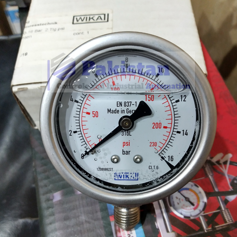 |
Featured Solution: WIKA Pressure GaugeModel: 232.50.100 |
Step 5: Match the Process Connection and Mounting Style
A pressure gauge must be structurally integrated into your piping grid via a reliable, leak-proof mechanical interface. You must match the thread standard, thread size, and layout configuration of your existing process ports.
1. Thread Standards:
- NPT (National Pipe Taper): The dominant tapered thread standard used heavily across American-designed plant infrastructure.
- BSPT / G (British Standard Pipe): Tapered or parallel thread geometries found extensively across European and Asian industrial machinery frameworks.
2. Thread Dimensions:
Ensure your connection matches the fluid volume and mechanical stress requirements. Common sizes include 1/8", 1/4", and 1/2" sizes. Small 63mm gauges typically use a 1/4" connection, whereas heavy-duty 100mm industrial process gauges require a robust 1/2" connection to handle physical weight and process loads safely.
3. Mounting Orientation:
- Bottom Mount (Lower Mount): The connection stem extends straight down from the bottom of the dial. This is the absolute standard for vertical pipe installations.
- Back Mount (Rear Mount): The connection stem projects out from the center or lower back of the gauge case, making it perfect for flush-mounting into control panels, cabinets, and automation consoles.
For high-demand process industries like power generation, marine applications, and large-scale manufacturing, selecting an elite brand with diverse connection configurations is paramount. High-performance Ashcroft Pressure Gauges Pakistan procurement teams order, such as the Ashcroft Pressure Gauges lineup, provide exceptional configuration flexibility alongside extreme safety features, making them a preferred choice for heavy-duty institutional engineering sectors.
Step 6: Identify the Required Accuracy Class
Not all processes require the same degree of accuracy. Higher accuracy instruments undergo far more rigorous manufacturing calibration protocols, which naturally impacts procurement budgets. Selecting the correct accuracy profile ensures you pay for exactly what your engineering thresholds demand.
Accuracy classes are typically defined by international norms such as ASME B40.100 (Grade A, B, 1A, 2A, etc.) or EN 837-1 (Class 0.6, 1.0, 1.6, 2.5). These figures represent the allowable margin of error as a percentage of the gauge's total full-scale span.
Industrial Accuracy Classification Breakdown:
| Industry Application Type | Typical Accuracy Class | Allowable Error Example (On a 0-10 Bar Scale) |
|---|---|---|
| Test & Calibration Laboratories | ±0.1% to ±0.25% Full Scale | ±0.01 to ±0.025 Bar (Ultra Precision) |
| Critical Process Loops (Steam, Oil, Gas) | ±0.5% to ±1.0% Full Scale | ±0.05 to ±0.10 Bar (High Accuracy) |
| Standard Industrial Machinery & MRO | ±1.6% Full Scale | ±0.16 Bar (Standard Industrial) |
| Commercial Water/Air Plumbing Lines | ±2.5% to ±4.0% Full Scale | ±0.25 to ±0.40 Bar (General Commercial) |
Step 7: Evaluate Specialized Measuring Technologies (Differential & Low Pressure)
Standard Bourdon tube gauges measure positive pressure relative to ambient atmospheric conditions. However, many specialized air handling, cleanroom, and filtration processes require distinct sensing technologies to track extremely subtle shifts or relative fluid balances.
1. Low-Pressure Capsule Gauges:
When working with low-pressure gaseous media below 600 mbar (such as commercial natural gas pipelines or burner systems), standard Bourdon tubes lack the sensitivity to flex cleanly. Instead, you must specify a capsule pressure gauge, which uses two corrugated diaphragms joined together to expand accurately under micro-pressures.
2. Differential Pressure (DP) Gauges:
In HVAC ventilation systems, cleanroom monitoring, and dust collection filtration units, engineers do not care about total line pressure; they need to track the difference in pressure between two distinct zones. Measuring the pressure drop across a filter element alerts maintenance crews exactly when that filter is clogged and needs replacement.
For specialized, ultra-sensitive low-pressure air handling or cleanroom differential tracking, standard industrial fluid gauges are insufficient. This is why checking the availability of a certified dwyer magnehelic gauge Pakistan standard stock item is essential. Precision airflow instruments like the Dwyer Magnehelic Differential Pressure Gauge operate via a frictionless magnetic movement, quickly responding to low positive, negative, or differential air pressures to prevent contamination risks in high-tech manufacturing spaces.
Source Certified Industrial Instrumentation from PAKCIA
Selecting the ideal pressure gauge requires balancing technical process constraints with long-term commercial efficiency. For industrial plants expanding infrastructure or sourcing mission-critical MRO replacements, having a knowledgeable local supply partner makes all the difference.
At PAKCIA, we stock a comprehensive inventory of certified mechanical pressure gauges, digital indicators, industrial transmitters, and specialized process instrumentation from globally trusted brands. Our dedicated technical sales engineering team is ready to evaluate your system parameters, verify material compatibility, and help you specify the exact configuration needed for your application.
Explore Our Catalog & Costs: Visit our main store to check competitive rates and see the latest pressure gauge price in Pakistan for our complete inventory of high-integrity pressure measurement devices.
Get a Technical Quote: Email your engineering specifications directly to info@pakcia.com to receive immediate, professional sales support.
Posted in:
Default category
Related posts
-
Industrial Valve Engineering & Procurement Guide: Most Commonly Used Valves across Pakistan's Process Industries
Industrial flow control systems represent the lifeblood of modern process engineering. Across Pakistan's rapidly...Read more
-
Pressure Transmitter Price in Pakistan: Complete Buying Guide, Types, Brands, Accuracy, Range & Applications
If you are searching for pressure transmitter price in Pakistan, the first thing to understand is that there is no...Read more
-
Advanced Flow Measurement Solutions in Pakistan: Industrial, Agricultural, and Commercial Applications
Pakistan is experiencing rapid industrialization, modernization of agricultural irrigation systems, and intensive...Read more
Leave a comment
Comments
zahid traders
By: Zahid On 07/12/2026hi, i liked this information. very detailed.
thank you.